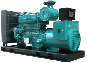
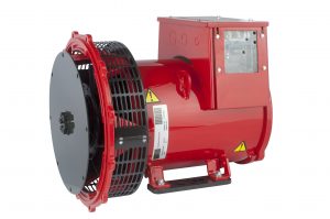
Condition Monitoring of Generator (Alternator)

The Alternator mainly has four major windings, Main Rotor (Field), Main Stator (Armature), Exciter Armature & Exciter Field. It also may have Permanent Magnet Generator too, hence fifth winding, PMG Stator. Out of these Main Rotors (Field), Exciter Armature & Permanent Magnet are rotating.
The type of construction of alternators is SPDP – Screen Proof Drip Proof. It means, the cooling air enters the alternator from one end, passes through all windings & then pass out from the other end. Because of this SPDP construction, few of the alternator failures are because of ingress of moisture in the winding. The other reasons for winding failures are Overloading or Highly Unbalance load.

The causes of functional failures of the alternator are mainly electrical, maybe excitation system connection issues or RRA circuit Diode/fuse failure or Faulty AVR (Automatic Voltage Regulator).
Other issues include Bearing Failures, Coupling Hub Failures, Rotor Stator Rub (Between Main stator & Main Rotor and between Exciter Field & Exciter Stator).
Condition Monitoring of parts of Alternator is same as that of the motor. The CM techniques include Vibration Measurement, Ultrasound Measurement & Thermography.
Our CM procedure for alternator parts, includes Visual Inspection, Electrical Inspection (online) – Current Monitoring – Excitation Current in respect to load current, Voltage Monitoring – Excitation Voltage in respect to Load Current, Thermography – All 5 winding temperatures & Inlet- outlet Air Temperatures, Harmonics detection Vibration Measurement – Misalignment, Rotor Unbalance, Rotor Rub, Vibration Probing Study – Rigidity of Foundation/ Base Rail Deformation/ Fastening issues, and Ultrasound Measurements for Bearings & Rotor Rub, Electrical Inspection (Offline) – Tan δ & Capacitance Testing and PI Testing – To monitor Winding Contamination & Insulation Degradation etc.

